Reversing the Xbox 360 Front Power Module: The SMC Two-Wire Interface
A look into the two-wire serial protocol used by the Xbox 360’s System Management Controller (SMC) for FPM communications.
Note: This post is based on a draft technical document originally written in 2023. Some details have been simplified or may be less comprehensive than in a finalized version.
Introduction
The Xbox 360 game console is the product of incredible engineering, being able to drive high-fidelity graphics that were unprecedented in a gaming console at the time. Examining the software and hardware intricacies, it was clearly developed by leading engineers at the forefront of the industry.
Focusing on the system hardware, there are many components that make up this system. This post focuses on one of the most intriguing user-facing components and its operating principles, the Front Power Module. The Front Power Module (FPM), or better known publicly as the RF board, is a daughter board responsible for handling three primary functions: turning the system on/off with a button, handling wireless communication for peripherals, and providing LEDs to notify the user of power, disk drive, and error status (if applicable).
This look will focus on the method of how the system controls the FPM LEDs, looking into the System Management Controller (SMC) and the protocol that connects both together. To conduct the research, the RF01 daughterboard and the Xbox 360 Xenon motherboard was used. However, this information is applicable to all RF board revisions across all console types (Original Xbox 360, 360 S, and E models) but may differ in commands.
Although this component is commonly referred to as the RF board by the community, I will refer to it as the Front Power Module (FPM), as that is a more accurate representation of its function. For consistency, it will be referred to as FPM throughout this post.
Overview of the FPM
The FPM is very simple and consists of the following:
A Power Button + LEDFour LED QuadrantsAn RF ModuleAn AntennaAn SPI EEPROM - Seemingly used for storing pre-defined error patterns?SiTel SC14470 - A proprietary baseband IC used for:Wireless peripheral communicationsSMC - FPM communicationsDisplaying controller, DVD drive and error states via LED quadrants
A programming header - Makes SC14470 UART and the two-wire interface easily accessibleAn Argon/Boron Port
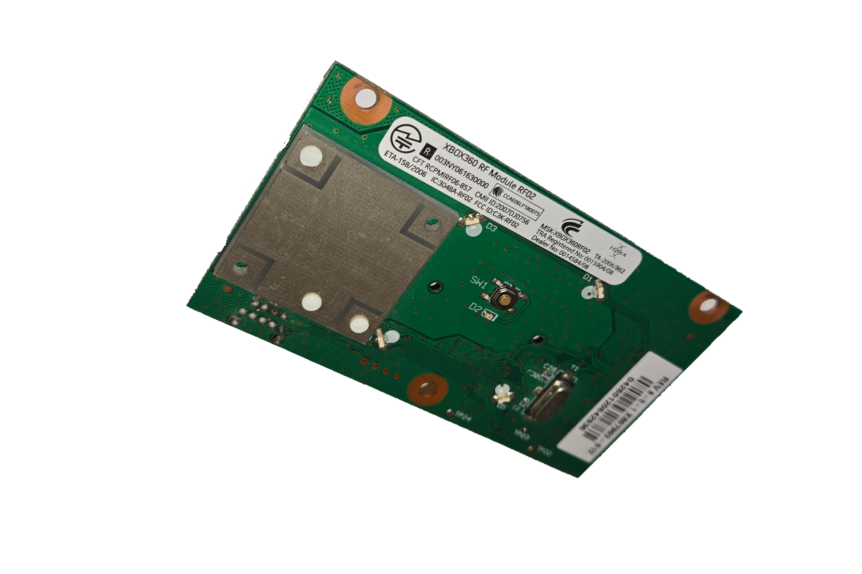
Top View (RF01 Model)
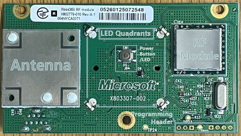
Image source: xenonlibrary.com1
Bottom View (RF01 Model)
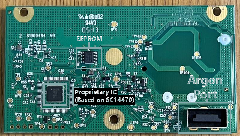
Image source: xenonlibrary.com1
Power Button
The power button is connected directly to the System Management Controller via the Argon/Boron port and handles the power on/off state.
LED Quadrants / ‘Ring of Light’
The four LED quadrants that surround the power button are known by the community as the ‘Ring of Light’. These four LEDs light up green to signify the controllers/players connected to the system. They can also light up red, which is used to signify error codes in the case that the console is not functioning properly.
SC14470 Controller
The IC shown on the bottom of the FPM is the controller, which handles everything, including the operation of the RF module, controller syncing and all the LEDs. This chip appears to be an SC14470 IC, or a proprietary variant derived from it. This can be seen on early prototype Argon FPMs.
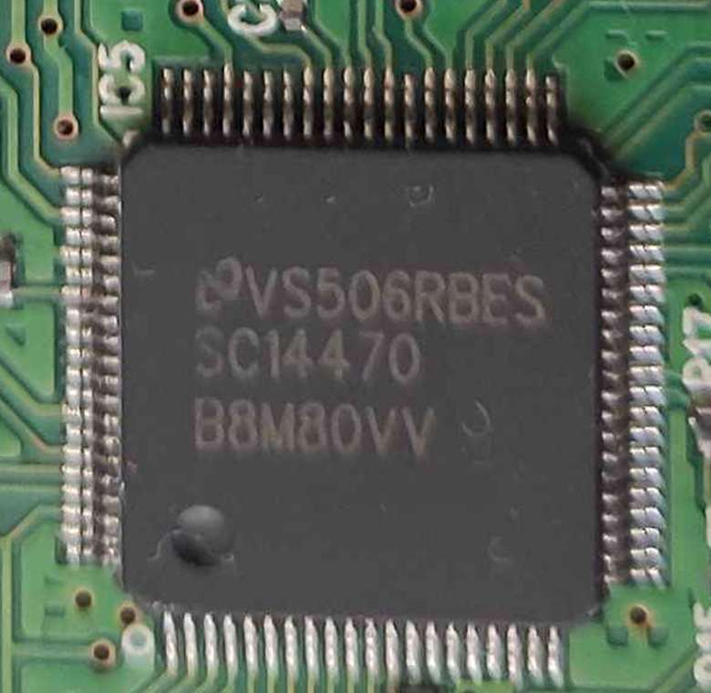
Information about this chip is scarce, as it appears that it was designed for Microsoft for this specific use. What is known is that the chip has UART for programming, as well as a custom two-wire serial interface used to allow the console to control LEDs and some other settings. There is also an SPI EEPROM chip located near the controller. Although it’s not confirmed, this EEPROM seemed to have the sole purpose of storing error patterns to be displayed on the Ring of Light (ROL) and doesn’t seem to be used.
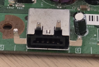
Argon/Boron Port
The Argon/Boron Port is a proprietary connector that connects the FPM to the main motherboard of the Xbox 360. The connector pins include:
VCC (3.3v)GNDPOWERSW(Connects FPM power button to SMC)ARGON_DP/BORON_DP(USB Differential Positive)ARGON_DN/BORON_DN(USB Differential Negative)ARGON_DATA/BORON_DATA(Data signal, part of the two-wire serial interface)ARGON_CLK/BORON_CLK(Clock signal, part of the two-wire serial interface)
The USB differential pairs connect to the southbridge. The RF module operates on USB and is handled by the Xbox 360 Kernel. This deals with any wireless peripheral, including wireless controllers. The ARGON_DATA/ARGON_CLK signals are part of the two-wire interface and connect directly to the SMC, which handles all other functions of the FPM.
The System Management Controller (SMC)
The SMC is a small Intel 8051 microcontroller embedded in the southbridge of the system. It handles most of the system, most notably the POR (Power on Reset) sequencing. Its job is to power on and off the system correctly, as well as transition between different power states. It also handles the disk drive status, the FPM, and other aspects of the system that will not be covered by this document. For more information related to the SMC, see XenonLibrary.
The power LED and LED quadrants on the FPM are completely controlled by the SMC and will be set depending on if the system is on or off, if the DVD drive is opening or closing, or how many controllers are connected to the system and their relevant player number.
When the system encounters an error, the SMC will put the system into an error state and will tell the FPM to display a specific error pattern depending on the error. This is done via the two-wire serial interface. If the system has an error which is triggered by the Xbox System Software (XSS), the XSS is capable of sending a message to the SMC via a FIFO, to inform that the system has encountered an issue and should display the relevant error code.
Two-wire Serial Interface
The two-wire interface is a basic, custom serial interface designed by Microsoft which has the sole purpose of allowing communication between the FPM and the SMC. It allows for bidirectional SMC-FPM communication.
Features
- Allows the SMC to communicate with the FPM and send commands that:
- Set the power and quadrant LEDs in different states. E.g Error states, DVD tray status
- Adjust quadrant LEDs based on console orientation (Determined by a tilt sensor on the main motherboard)
- Enables and disables the wireless radio
- Begins the controller syncing process
Note: For clarity,
ARGON_CLKandARGON_DATAwill be referred to asCLKandDATArespectively.
The interface consists of a CLK signal (usually 250kHz), as well as a DATA signal. These signals are used to send 9-bit commands in either direction. Each bit sent in a command is represented by the DATA pin being pulled high (1) or low (0) on the falling edge of a clock pulse and should have a pulse width of one clock pulse.
Command Sequence
- Initiator pulls
DATAline low - FPM generates 250kHz
CLK - First bit: Acknowledgement
0= SMC sending1= FPM sending
- 9-bit command follows
- Conversation ends when both
CLKandDATAare pulled high
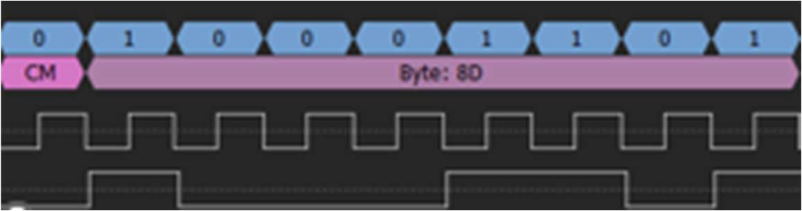
Example Command Sent: 010001101
This tells the FPM to flash the power LED and initiate the boot animation.
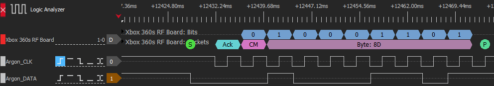
As you can see, the CLK and DATA signals are pulled up to 3.3v when standby power is asserted to the console to set a default state. The initiator of the conversation (the SMC in this case) begins by pulling down the DATA line to let the two devices know that a command is inbound.
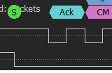
The FPM will start to generate a 250MHz CLK signal with a 50% duty cycle and uses the first clock cycle to read an acknowledgement bit. The sender of the command can be determined by this bit. If the acknowledgement bit is low, this signals the FPM that the SMC is sending a command. If the bit is high, this tells the SMC that the FPM is sending a command or data. The following image, in this case, displays that the acknowledgement bit for this command is 0 and signifies that the SMC is sending a command to the FPM.
The 9-bit command then follows, where the next 9 clock cycles represent the bits of the command and should be determined by the high or low state of the DATA signal. In the case of the example shown, the command that was sent was 010001101. This specific command tells the FPM to start flashing the power LED and to initiate the boot animation programmed into the FPM.
Connecting to the Interface Externally
The FPM daughterboard can be interfaced via the two-wire interface using any device, due to its simplicity. The most popular device is the Raspberry Pi Pico, due to its speed and flexibility. Here are diagrams displaying how you can connect the FPM to a Pico:
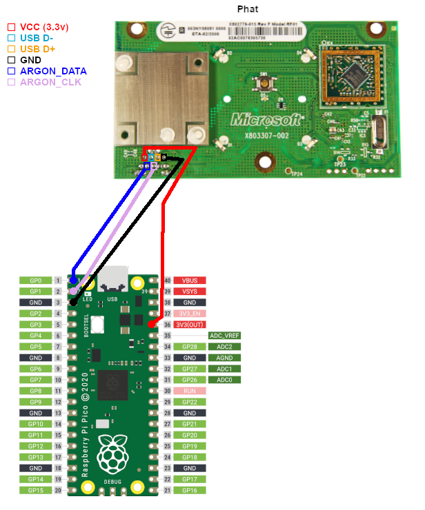
Image source: EmiMods2
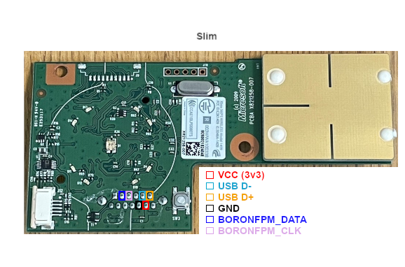
Image source: EmiMods2
Sending Commands
The protocol implementation can be quickly implemented in MicroPython. If you have never used MicroPython before, please take a look at the official documentation on the Raspberry Pi website.
Here is some basic Python which can send commands to the FPM:
from machine import Pin
from time import sleep

//Definition of CLK and DATA pins. Change pins respectively
argon_clk = Pin(18, Pin.IN, Pin.PULL_UP)
argon_data = Pin(19, Pin.OUT, Pin.PULL_UP)
led = Pin(25, Pin.OUT)

argon_data.value(1)

//Sending command function
def send_to_argon(cmd):
    cmd = cmd.replace(' ', '')
    argon_data.value(0)
    for i in range(10):
        while argon_clk.value() == 1:
            pass
        argon_data.value(int(cmd[i]))
        led.value(int(cmd[i]))
        while argon_clk.value() == 0:
            pass
    print(f"Command {cmd} sent!")
    sleep(0.0025)
    argon_data.value(1)
    sleep(0.1)
Commands List
| Command Bits | Description |
|---|---|
| 010000000 | Turns off all LEDs |
| 01000010 X | Turn on power LEDX: If X is 1, the LED animation will play |
| 01000100 X | Turn off power LEDX: If X is 1, the LED animation will play |
| 01000110 X | Blinks power LEDX: If X is 1, the LED animation will play |
| 010010000 | Takes the FPM out of an error state |
| 01010 X3 X2 X1 X0 | Set green quadrantsX3:0: Represents the quadrants to set green |
| 01011 X3 X2 X1 X0 | Set red quadrantsX3:0: Represents the quadrants to set red |
| 0110 X4 X3 X2 X1 X0 | Display error code on ROMX4:0: Error pattern number |
| 00100 XXXX | EEPROM read from location XXXX |
| 00010 XXXX | EEPROM write to location XXXX |
| 0000100 X1 X0 | Changes console orientation and radio statusX0: 0=Horizontal, 1=VerticalX1: 0=Turns radio off, 1=Turns radio on |
| 000000100 | Starts controller binding |
| 00000100 X | Turn on or off wireless controllers after system initializationX: If X is 1, controllers stay connected |
Here is an example of using the code snippet:
def bind():
    send_to_argon("0000000100")

bind()
The example RP2040 micropython code can be found on my Github
Glossary
Argon – Codename for the first FPM during development. Signal labels prefixed with ARGON_ reference this hardware, but was used throughout the revisions of the Original Xbox 360.
Boron – Codename for the FPM that was developed for the Xbox 360 S console. Functionally similar to Argon, and other FPMs, but with updated hardware integration to meet the design specifications of the newer console design. Signal labels are prefixed with BORON_.
FPM (Front Power Module) – The daughterboard responsible for power control, LED indication, and wireless peripheral communication. Commonly referred to as the RF board by the community.
SMC (System Management Controller) – An Intel 8051 microcontroller embedded in the southbridge, responsible for power sequencing, LED control, and various low-level system tasks.
ROL (Ring of Light) – The four-LED quadrant system surrounding the power button, used to indicate player number or error states.
XSS (Xbox System Software) – The operating system layer of the Xbox 360, responsible for user interface, applications, and higher-level control of hardware.
SC14470 – A proprietary baseband IC found on the FPM, used for managing wireless communication and interfacing with the SMC via a custom two-wire protocol.
For deeper technical documentation pertaining to these components, please visit XenonLibrary